


Part 2: So you wanna open a Gigafactory ….
Part 2: So you wanna open a Gigafactory ….
Not so fast “coating”
So you wanna open a Gigafactory ….
Not so fast “coating”
Battery production is not as straightforward as turning ON the manufacturing line. There are many subtle nuances that can make or break your business, control of these nuances takes years of battery production experience. Unfortunately there is a dearth of experience in Europe and US when it comes to mass producing batteries. Where will they find this experience? most likely by poaching engineers from the dominant Asian manufactures. In the meantime Electrios is happy to share our notes and lessons learned during our work with Asian battery manufacturers in the hope of accelerating the global battery industry.
Li-ion battery electrode coating
In part one of our series we discussed the importance of preparing quality slurries, necessary for uniform electrode coating. In the second part of our installment we discuss the electrode coating process. The coating process is a key bottleneck in battery production as well as the costliest (~ 30%).
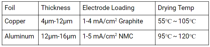
In essence the coater evenly applies the active material onto the current collector; namely aluminum foil in the cathode case and copper foil for the anode. Depending on the electrode requirements coating thickness varies from thick films (>100µm) used for energy cells or thin films (<100µm) used for power cells. Each presents a unique set of coating challenges. The quality of the coating is directly related to the capacity and ultimately battery performance.
The equation below can be used to design the electrode according to the battery specifications. Coated electrode capacity C is related to the following
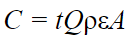
Where electrode thickness (t), specific capacity of the electrode material (Q), bulk density of the active material (ρ), active material fraction (Ɛ), electrode area (A).
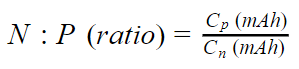
Using the electrode capacities we can calculate the N:P ratio. Generally the negative electrode (N) is oversized in relation to the positive electrode (P); this is known as the N:P ratio. Oversizing helps avoid lithium plating on the negative electrode and irreversible capacity loss. Industry practice maintains the N:P ratio within the following range (1.0–1.2).
Process controls
1)Coating uniformity If the electrode density is too low, capacity will not reach the nominal capacity. On the other hand if it’s too large the excess lithium may lead to plating and raw waste materials.
2) Coating thickness Too thin or too thick coats will affect the electrode rolling process, consistency, internal resistance and battery performance.
3) Alignment Misalignment may cause a sizing mismatch between the positive negative electrodes and not fully utilize all the available capacity.
4) Baking stability (uniform temperatures) If the drying temperature is too low during coating, electrodes will not be completely dried. High temperature may cause the solvents to evaporate too quickly leading to cracking and flaking.
5) Adhesion Between the foil and electrode material. Maintain dynamic tension control throughout the coating process to ensure good adhesion and lower internal resistance.
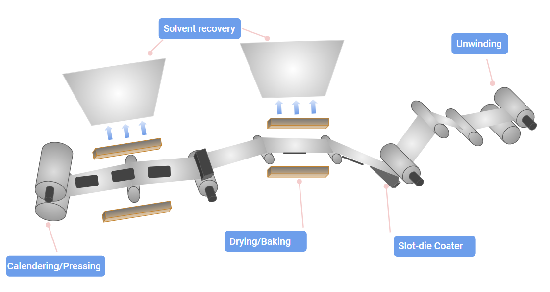
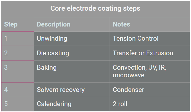
Coating Process
Foils should be thoroughly inspected to ensure a flat clean surface, no obvious bumps or scratches. The presence of dust, debris or other particles can cause short circuits within the battery. Check copper foil and aluminum foil conductivity and the presence of oxides on the foil surface which affects conductivity.
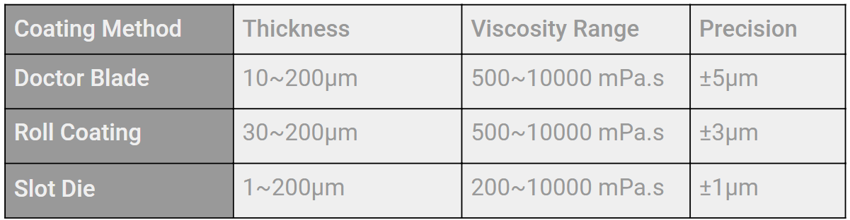
The coat is applied as the foil passes between the coating roller and the doctor blade, the gap between the doctor blade and the substrate determines the thickness of the coating. This method allows control of the coating amount and coating accuracy and is suitable for highly viscous slurries with high solid content.
Roll coating involves a 3-roll reverse roll coating system. Coating is applied to the foil as it passes between the support roller and application roller. The doctor blade controls the amount of slurry transferred and thickness. Roll coating is mostly used by the consumer lithium-ion batteries industry.
Slot die coating
The basic principle of slot die coating, is slurry extrusion along the gap of the coating die under a pressure to the foil. Die head size vary from 750mm->950mm->1200mm->1600mm. Slot die advantages include fast coating, high precision, uniform thickness; closed system and high slurry utilization. Slot die coating is mostly used by the power battery industry.
Coating Uniformity
Coating uniformity is used to evaluate the overall quality of the coating, in both
the lateral and longitudinal directions. As these dimensions are not symmetrical, binder requirements are very different. Binder rule of thumb; larger the width of the substrate, the more difficult it is to control the lateral uniformity. From practical experience electrode widths <80cm, uniformity is easier to control; as the width increases above 130cm lateral uniformity is difficult to control. As production lines increase, longitudinal uniformity will become a greater challenge than lateral uniformity.
Coating speed
The speed of the coating machine is getting higher and higher, from the initial 15m/min, 25m/min to 50m/min, 80m/min and above. The need for speed brings its own difficulties with process control and front and back alignment control.
Common coating defects
The industry demand for high capacity production lines require foils to be coated at ever increasing speeds(>90m/min), making maintaining defect free high quality electrode production an ongoing challenge. Defects increase the electrode scrap rate and drive up the cost cell manufacturing.
Blister defects Foreign matter such as dust is mixed into the coating liquid or falls on the surface of the wet coating, where the surface tension of the coating is affected. The intermolecular forces may leave a circular outline with a thinner interior after drying.
Pinholes Bubbles are introduced during stirring, transportation and coating processes. The pinhole defects arise when trapped bubbles rise from the inner layer to the surface where they burst leaving an open path between the foil and electrode surface.
Scratches Due to foreign matter or large particles stuck in the slit gap or coating gap, low quality foil, coating gap blockage between the coating roller and the back roller, damaged the die edge.
Thick edges The reason for the thick edges is driven by the surface tension of the slurry, which causes the slurry to migrate to the edge.
Particle agglomeration Particles not fully dispersed in solution.
Future coating outlook
As the battery industry grows so too will the demands on coating equipment. The coating industry needs to develop high speed equipment, increase utilization rates, improve quality by integrating online process controls. We believe extrusion coating will continue to dominate due to its high precision, uniform coating, and large width suitability.